The tools needed for the job are:
- T5 Torx river.
- x-acto knife.
- Small wire cutters.
- High quality soldering tool.
- Light duty rosin core solder.
- Paper cup (for parts).
- Your new antenna jack.
Follow the instructions in the previous entry regarding disassembly of the treo 650. The first task after disassembly that needs to be done is to cut a piece of plastic from the midsection. This needs to be done because the rear shell will not snap into place once the antenna is soldered into position. Previously in the unmodified Treo 650, the antenna was installed after the 2 shell halves were assembeled. Below is a picture showing what the midsection looks like before modification.
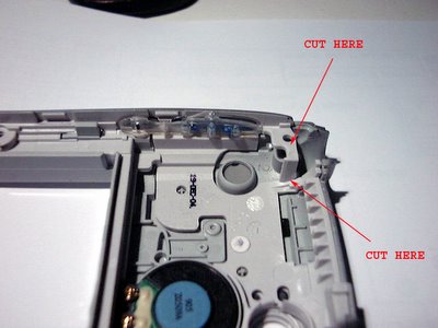
And here is a picture showing what the midsection should look like after its cut.

Next up is to install the antenna. This is pretty easy, but if you get it wrong, you will not be able to assembly your Treo correctly. After various iterations, I settled on 26 guage stranded wire. More info to come on the antenna in my next post. Below is an assortment of Treo 650 antennas.

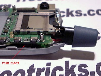
The antenna now has to be installed before the rear shell in installed. The most critical part is the wire routing. Below is a picture of where the antenna should be with the wires soldered in and no slack in the wires. You should not be able to pull the antenna out farther than what is pictured but it can't be shorter either. The wires should be routed behind the foam block so they do not interfere with the volume buttons.
Next route the white and red wire behind the screw boss and the black wire in front as shown in the picture below. You may need to trim the boss on the right side to make room for the wires. The mainboard needs to sit on the boss flush so make sure the wires do not interfere.

Now the picture below shows where the wires go. Make sure they are the right length and routed correctly before you solder them. I used a high quality Miller solder station set to 240 C and a fine tip. If you don't have anything like this avalible, I would recommend a butane one, but make sure the tip is long enough so at the butane does not burn anything.

Make sure you short the leads labled as "BRIDGE", this is needed if you want to use the stereo headset for phone calls. If you do not do it, your internal mic will be disabled with headphone use. The white wire can alternativly be soldered to the lead labled s, but it will disable the left channel on the new jack when using the original jack. You might also encounter problems in the future if there are problems in the jack. M is for mic, which shorts to ground when a connector is inserted, but in this case will be shorted by the bridge. Mono headset with mic will still work... trust me!
Below is a picture of how you could route the wires.

I recommend wiring the white wire to the second lead "WHITE", not to the top one as shown. Also the black wire routes better over the red wire. You may have to tinker with the wire routing a bit.
Now you need to assemble the rear shell. You will need to be carefull to make sure that the wires stay in place and do not interfere. Once you snap the rear shell at the six places, you should carefully insert the antenna and use the longer screw to secure it. Then secure the rest of the screws and you should be done!
Well, that is it. I will post the antenna info later, maybe after the Holidays if I take off this weekend. Please let me know if there are any mistakes or hints.
Come back for other hacks and tricks... I have better ones almost complete.
posted by TreoTricks at 8:48 PM
![]()
![]()


3 Comments:
Sometimes I shoot hot load of boy spunk all over my cat Gladys.
Do you want to lick her clean?????
you are amazing! how do you figure this stuff out?!?!?!?
way cool mod - have you done this to a treo 700w? if so, are the pins same? for red, white & blace - and also is bridge solder same?
thanks!
Post a Comment
<< Home