- T5 Torx driver.
- x-acto knife.
- Small wire cutters.
- Soldering tool.
- Light duty rosin core solder.
- 26 guage stranded wire, red, white and black.
- Audio jack, Kycon P/N ST-3500-3N.
- Dremel tool.
- Dremel cutting bits, 1/8" & 3/32"
- hand drill or low power drill.
- Drill bits, 0.195", 0.125" & 0.060"
- Small rat tail file.
- Small hammer.
- Donor Antenna.
First thing you need to do is disassemble the donor antenna, this is done by drilling the top of the antenna with a 0.125" drill bit. Drill the hole right in the middle until you break thru. Then remove the bit and insert it into the drilled hole all the way down. Find a nice hard, sharp edge on a workbench or vise or anything else that will work. Place the antenna cover lip on the edge as shown in the picture below and give the drill bit a good whack to remove the antenna core from the cover.

Below is a picture of the 2 pieces separated.

Now you need to remove the actual antenna, screw, and antenna contact. After removing the screw, you need pull up on the gold plated antenna contact and pull it out. Remember how it comes out, so you do not try to insert it in backwards later. Now unpeel the antenna and set it aside. Try not to contaminate the adhesive since it will be reusable.

Now here comes the hard part, cutting away at the antenna core and audio jack. Although a 4 pole 2.5mm audio jack fits perfectly in the antenna core, the Treo already has one of those. You can use a 2.5mm jack if you don't want to cut away any plastic.
When cutting, remember that the more you cut on one, the less you need to cut on the other. I is a good idea to have at least extra jacks and maybe an extra antenna. I have ruined a couple but now I can do them in my sleep. Just work slowly and jump back and forth to make sure you do not cut too much. I recommend cutting at slow speeds.... 25K RPMs is way too fast. Start with the bigger bit and switch to the smaller one to finish up.
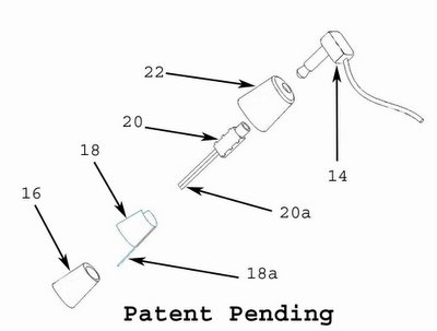
For cutting away material, work on making the hole in the antenna core square and trying to make the audio jack round. Start by cutting the tabs off the audio jack and rounding the corners. You may have to get a bit agressive and cut into the contacts but don't worry, they are relativly secure. Next cut 3 sides off of the end as indicated in the picture below, labled "shorten". You will need to cut about 1/8" on the sides with no metal. You will also need to cut about 1/16" or more of the contact for the connector tip on the 4th side. Also cut the groove shown in the picture. Also take some material off of the top side of the connector, from where the "cut groove" arrow is to the left. After cutting the jack... it doesn't even look the same.

Now jump to the antenna core. Start by converting the semi-round into a square. Cut away at the corners and make them sharper. Try not to cut away material from the side where the screw goes it. Even though the screw will not be reused, that side is the strongest and does most of the support. Also, at the bottom of the hole there is a protrusion also on the side of the screw hole. Try not to remove any material from there because if you do, you might pick up noise from the antenna. That protrusion is the channel that the gold plated antenna contact sits in. Below is a picture showing how much is cut. Also note the hole for the jack wires.

Once you think you cut enough from both pieces, try to see if the jack slides into the core. don't use too much force, it should slide in snug but not too snug. Make sure that when you insert the jack in, it is oriented with the contact for the tip (white wire) on the opposite side from where the screw hole is. The jack should go in almost all the way in, with just the round portion of the jack sticking up.
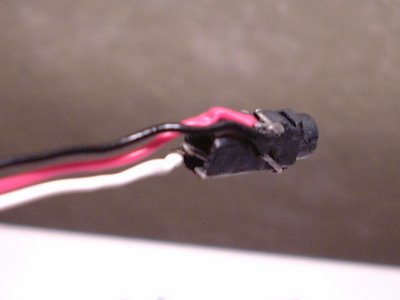
Once you think you have cut enough material from both pieces, it time to solder on the wires. The pieces should be at least 4" (10 cm) long. The black wire goes closer to the insertion hole and sits in the channel. Make sure that the portion of the wire does not have insulation, otherwise the jack might not go in. The red wire goes on the middle contact and the white wire goes on the tip contact. There might not be too much metal on the tip contact, so be very careful that after soldering, the jack still functions. You should check the jack many times throughout the assembly process. below is a picture of what the jack should look like all wired up. Wires look a bit beat up since this is a prototype that has been worked on a bunch.
Now insert the wires and the jack in the antenna core. Do not be too forcefull, you can still cut away some material. If you are having a hard time removing the jack because it is stuck, use a pick or someting similar and insert it via screw hole and pry out the jack. Once you get a good fit you should seal up the screw hole to insulate the audio jack from the antenna. I used some plastic and an old solder tip and heated up a small piece until it was soft, then I covered up the hole and cut away the excess once it hardened.
Now go ahead and stick the antenna back on and then insert the gold plated antenna contact back in where it goes. Since the screw no longer can be used, you will need to solder the 2 pieces together. Just break off a piece of solder and place it between the 2 pieces and heat the contact until the solder flows and then bonds together.
You are now ready to put the cover back on. This process can take up to an hour or more... and that is with practice and experience. I have a tool and a drill press to drill it just right, but you should file and cut a little bit at a time, checking after every cut to make sure you get a perfect fit. If you think you have it centered pretty good, you can use the correct sized drill bit and be done with it.
Place the cover on how it is suppose to go on for placement check and backwards (or with another jack) to see if it is the right size hole. Once you think you have it right, squeeze the 2 halves togheter until they snap together.... and stand back and admire your work. Good JOB!!

It ther are any errors or suggestions or questions please let me know via email. I have received some questions but with no return email address.
Up next, optimizing the antenna for 1900 MHz, an increase in battery capacity, integrated hotsync button and even better hacks than this one... stay tuned!!!
posted by TreoTricks at 1:19 AM
![]()
![]()


13 Comments:
verry nise. what is next?
you seem to be obsessed with holes. have you considered just getting a girlfriend and enjoying holes the way god intended?
you really need to disable anonymous comments here. People might say things like fuck or shit or cock sucking whore bitch of satan. you know what I mean?
oh, I just thought of another one: cherry gobstopper for plugging the rectum of jesus.
See what awful things people could write unless you take steps to prevent them? Yes sir, I do heartily recommend you take my advice immediately.
Is this really the only space available for a 3.5 jack?
Nice... so now all the radiation that's supposed to be dissipated can instead by funneled right into your ear since in this case, your external headphones will also be an antenna extension.
Sound like a great idea, but the consequenses could be bad. I'll wait til you get the patent approved before I sue. :)
I have worked on many antennas, 2 for the U2 (in sunnyvale!), so I know a thing or 2.
Tesing has been positive... The jack is insulated from the antenna. Much less harmfull that using the phone as it was intended. Test it yourself...
Patent is one thing, product liability is another. You don't need a patent to be liable, and patent holders are not liable. I would guess someone implementing a hazardous design would be liable...
Thanks for your input though....
There is no way I have the skills to do this. How much do you charge to do it for me? My 2.5 audio jack has worn out on me and I don't want to send it in for a refurbished one because it will probably have even worse issues!
Incredibly cool!
Do you have any insight into doing something similar for the Treo 600?
By the way, like another poster said, I think I would mess something up if I tried it myself. You should definitely consider doing it as a service for people.
TreoTricks, This antenna hack is awesome. Thank you much for your clear cut articles! I am not a treo user, but have used your tutorial to fix a friends treo and all went well.
Hi,
Seems agreat idea. I miss information as to where you solder the other end of the wires to on the PCB - or did I miss something!!
Alan
I've just successfully completed the mod myself. took a few hours. however, i do not get 'full' sound until i plug in something to the 3/32" jack. I guess because there is a connection that gets made when a headphone is plugged in. How do I emulate this, so i dont have to do this when my 1/8" headphone is plugged in?
Ok, I found where the links to this are... (You can ignore my previous question on another comments section.) You weren't kidding when you said this was a risky business to do... I'll have to get a spare antenna before I try this... Nice job... I like the idea of putting it into the antenna so there is only one protusion form the body of the phone. (As opposed to two on opposite ends when using the jack on the other end.)
Post a Comment
<< Home