Thursday, December 22, 2005

Treo 650 Antenna for sale on eBay

Treo 650 antenna for sale on eBay

I decided to put up one of my prototype antennas up for sale. Buyer will have a choice of either blue or gray. The hardest part of the 3.5mm audio jack hack is making the antenna... The installation is easy.

Check out the ebay link for more info HERE


Tuesday, December 20, 2005

Happy Holidays!


Click HERE to see my postage stamps for sale

Thursday, December 15, 2005

Send Free SMS messages

Send Free SMS Messages

I came across this service and I was impressed. It is called TeleFlip. It allows one to send free SMS messages to any capable mobile number in North America via email, without knowing the carrier of the mobile.

I partly thought this was an excellent idea because I came up with a similar idea about five years ago. I planned on using a database like the one used at www.fonefinder.net that tells you what carrier the number belongs to. While this might have worked 5 years ago, the rumors of numbers portability (the ability to tace your number with you) scared me away so I didn't bother to work on it further or persue a patent. I now patent all my good and I guess not so good ideas.

I was even fortunate enough to have found a good domain name... fastbeep.com. I used it for 2-3 years for personal messaging and then just let it expire. Walt at fonefinder did not think it would work with portable numbers, but it did.

Anyway, the usage is very easy especially for us treo users. You just simply send an email it the format (xxx) xxx-xxxx@teleflip.com. You can have the number in any format actually, with spaces or no spaces, or just the 10 digits. The service receives the message and sends it to the appropriate carrier. Charges may apply from the carrier for the recipient and may be subject carrier restrictions.

You can use this service in many different ways. Send group messages, send timed messages, forward important emails, etc...

Check it out at www.teleflip.com and let us know how it works!

Sunday, December 11, 2005

Treo 650 Audio Internal Impedance fix for FM Transmitters and more.

I came up with this idea yesterday along with another real good one. I still have to test the other one, so you guys will probably see it next year but it's very useful and very easy! also woking on optimizing the antenna, making an internal antenna and a bunch of other stuff.

It seems many people are using the Treo 650 for their audio needs. This is great since the Treo 650 has great potential as an audio device, but it does needs some help. It also doesn't help that the CEO chooses to use an ipod instead of optimizing the Treo or his favorite Palm, the Lifedrive, but that is another story.

So, some people out there are using an FM transmitter, but to get it to work, you need to use a 2.5mm male to 3.5mm female stereo adapter AND some also need to use an audio coupler adapter like the one Seidio sells online. Just because you have audio out it does not mean that the FM Transmitter will work as a speakerphone, so test it to make sure.

I had an Belkin adapter around so I tested it via my 3.5mm audio jack and it worked, but not as a speakerphone like some of the other people were using it for, so I needed this hack.

The tools needed for the job are:

  1. Small Phillips head screwdriver.
  2. Small wire cutters.
  3. Soldering tool.
  4. Light duty rosin core solder.
  5. 1000 ohm resistors, 2X.
  6. Ohm meter.

The solution seems simple according to the forums on the internet, but I don't like adapters and refuse to use them. I then came up with the idea to take apart the Belkin FM Transmitter and add resistors to decrease the impedance the Treo sees to get it to work.

What you need as far as impedance (resistance) for any device to work propery is 500 ohms or less between ground and both channels, indicated by the red arrows for the right channel and blue for the left channel. White is the usual color used to indicate left channel, but it does not show up too well in pictures. I tested the FM Transmitter and got a reading of 1000 ohms. To decrease it to 500, just solder in resistors of 1000 ohms in parallel. For other devices that show very high resistance, like my powered speakers @ 10k ohms, just use 500 ohm resistors.

This solution would mean no adapter for me. It took me less than 10 minutes to do this hack since I had the soldering station and the right resistors by my side. You should also change the connector to a 2.5mm one if you are just using the FM Transmitter on the Treo... or do my 3.5mm Audio Jack Hack.

First thing you need to do is take apart your FM Transmitter. Just take off the battery cover, the batteries and remove the phillips head screw indicated by the red arrow in the picture below.


After removing the screw, split the two halves apart as shown below. You should not have to disassembly any further but you could for ease of soldering.

Now you need to solder in the resistors in between ground and the left channel, shown in blue in the picture below. You also need a resistor between ground and the right channel, shown in red below. Place the resistor for the left channel on top and place the one for the right channel between the board and the casing.

Put the FM Transmitter back together and that is it. Test it for audio and for speakerphone use to make sure that it works.

You can do this hack on almost any audio device like powered speakers, bluetooth audio transmitter, casette tape adapter, etc...


Wednesday, December 07, 2005

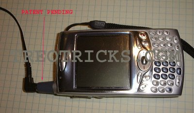
Add an Extra Audio Jack to Your Treo, Part 3.

This is the final how-to for the Antenna Jack Hack. I do have one more how-to for modifying the antenna element 18, but that will come at a later date after more testing. My intent is to optimize the antenna for 1900 MHz spectrum.


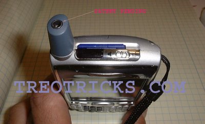
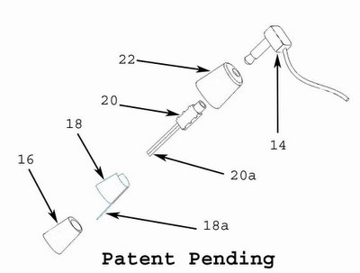
Please read the entire article to make sure you know what you are getting into and understand the proceedure. To get the antenna ready for installation, you will need to enlarge the hollow area of the antenna core 16 and also drill a hole for the audio jack wires 20a, you will need to solder 18 and 18a together, cut and trim down the audio jack 20 and solder the wires 20a, and to cut an acess hole in the antenna cover 22.


The tools needed for the job are:
  1. T5 Torx driver.
  2. x-acto knife.
  3. Small wire cutters.
  4. Soldering tool.
  5. Light duty rosin core solder.
  6. 26 guage stranded wire, red, white and black.
  7. Audio jack, Kycon P/N ST-3500-3N.
  8. Dremel tool.
  9. Dremel cutting bits, 1/8" & 3/32"
  10. hand drill or low power drill.
  11. Drill bits, 0.195", 0.125" & 0.060"
  12. Small rat tail file.
  13. Small hammer.
  14. Donor Antenna.

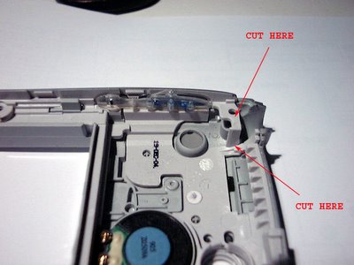
First thing you need to do is disassemble the donor antenna, this is done by drilling the top of the antenna with a 0.125" drill bit. Drill the hole right in the middle until you break thru. Then remove the bit and insert it into the drilled hole all the way down. Find a nice hard, sharp edge on a workbench or vise or anything else that will work. Place the antenna cover lip on the edge as shown in the picture below and give the drill bit a good whack to remove the antenna core from the cover.


Below is a picture of the 2 pieces separated.

Now you need to remove the actual antenna, screw, and antenna contact. After removing the screw, you need pull up on the gold plated antenna contact and pull it out. Remember how it comes out, so you do not try to insert it in backwards later. Now unpeel the antenna and set it aside. Try not to contaminate the adhesive since it will be reusable.

Now here comes the hard part, cutting away at the antenna core and audio jack. Although a 4 pole 2.5mm audio jack fits perfectly in the antenna core, the Treo already has one of those. You can use a 2.5mm jack if you don't want to cut away any plastic.

When cutting, remember that the more you cut on one, the less you need to cut on the other. I is a good idea to have at least extra jacks and maybe an extra antenna. I have ruined a couple but now I can do them in my sleep. Just work slowly and jump back and forth to make sure you do not cut too much. I recommend cutting at slow speeds.... 25K RPMs is way too fast. Start with the bigger bit and switch to the smaller one to finish up.

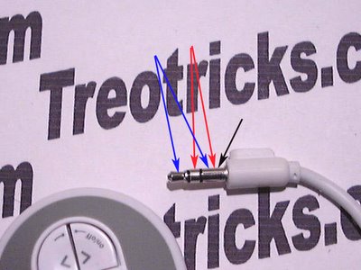
For cutting away material, work on making the hole in the antenna core square and trying to make the audio jack round. Start by cutting the tabs off the audio jack and rounding the corners. You may have to get a bit agressive and cut into the contacts but don't worry, they are relativly secure. Next cut 3 sides off of the end as indicated in the picture below, labled "shorten". You will need to cut about 1/8" on the sides with no metal. You will also need to cut about 1/16" or more of the contact for the connector tip on the 4th side. Also cut the groove shown in the picture. Also take some material off of the top side of the connector, from where the "cut groove" arrow is to the left. After cutting the jack... it doesn't even look the same.

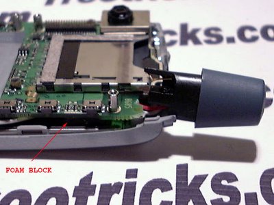
Now jump to the antenna core. Start by converting the semi-round into a square. Cut away at the corners and make them sharper. Try not to cut away material from the side where the screw goes it. Even though the screw will not be reused, that side is the strongest and does most of the support. Also, at the bottom of the hole there is a protrusion also on the side of the screw hole. Try not to remove any material from there because if you do, you might pick up noise from the antenna. That protrusion is the channel that the gold plated antenna contact sits in. Below is a picture showing how much is cut. Also note the hole for the jack wires.

Once you think you cut enough from both pieces, try to see if the jack slides into the core. don't use too much force, it should slide in snug but not too snug. Make sure that when you insert the jack in, it is oriented with the contact for the tip (white wire) on the opposite side from where the screw hole is. The jack should go in almost all the way in, with just the round portion of the jack sticking up.

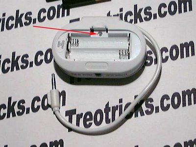
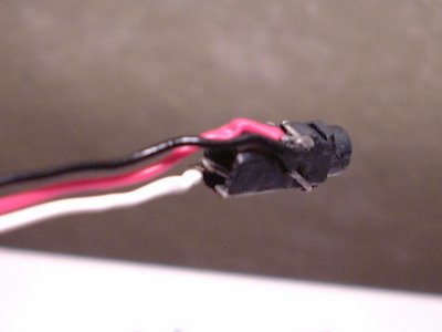
Once you think you have cut enough material from both pieces, it time to solder on the wires. The pieces should be at least 4" (10 cm) long. The black wire goes closer to the insertion hole and sits in the channel. Make sure that the portion of the wire does not have insulation, otherwise the jack might not go in. The red wire goes on the middle contact and the white wire goes on the tip contact. There might not be too much metal on the tip contact, so be very careful that after soldering, the jack still functions. You should check the jack many times throughout the assembly process. below is a picture of what the jack should look like all wired up. Wires look a bit beat up since this is a prototype that has been worked on a bunch.


Now insert the wires and the jack in the antenna core. Do not be too forcefull, you can still cut away some material. If you are having a hard time removing the jack because it is stuck, use a pick or someting similar and insert it via screw hole and pry out the jack. Once you get a good fit you should seal up the screw hole to insulate the audio jack from the antenna. I used some plastic and an old solder tip and heated up a small piece until it was soft, then I covered up the hole and cut away the excess once it hardened.

Now go ahead and stick the antenna back on and then insert the gold plated antenna contact back in where it goes. Since the screw no longer can be used, you will need to solder the 2 pieces together. Just break off a piece of solder and place it between the 2 pieces and heat the contact until the solder flows and then bonds together.

You are now ready to put the cover back on. This process can take up to an hour or more... and that is with practice and experience. I have a tool and a drill press to drill it just right, but you should file and cut a little bit at a time, checking after every cut to make sure you get a perfect fit. If you think you have it centered pretty good, you can use the correct sized drill bit and be done with it.

Place the cover on how it is suppose to go on for placement check and backwards (or with another jack) to see if it is the right size hole. Once you think you have it right, squeeze the 2 halves togheter until they snap together.... and stand back and admire your work. Good JOB!!


It ther are any errors or suggestions or questions please let me know via email. I have received some questions but with no return email address.

Up next, optimizing the antenna for 1900 MHz, an increase in battery capacity, integrated hotsync button and even better hacks than this one... stay tuned!!!

Monday, December 05, 2005

Add an Extra Audio Jack to Your Treo, Part 2.
I will describe what it takes to install a modified antenna with audio jack into your Treo 650. The same proceedure should work for the new Treo 700 based on internal pictures I have seen. I changed the title of this article because the period in the title (3.5mm) was causing the blog entry title to be shortend and also because this hack can be done to integrate a 2.5mm audio jack as well. Please read the entire article and make sure you understand it before proceeding.

There are 3 major tasks that need to be done to install a modified antenna: Plastic needs to be cut from the midsection, wires need to be routed precisly and cut to a precise length, and the wires need to be soldered to the existing jack. Optionaly, a jumper needs to be soldered in to be able to use the internal mic and stereo headphones on a phone call. This is highly recommended but disables the functionaliy of the mic on the special 2-in-1 headset.

Make sure you have a well lit workspace, with plenty of room to work in and a place to keep your tools and disassembled parts. I would avoid carpeted areas just in case you drop a screw or some other small part. Also, make sure your workspace is ESD safe and avoid getting up too often and increasing the possibilites of generating a static discharge and zapping your beloved treo.

The tools needed for the job are:
  1. T5 Torx river.
  2. x-acto knife.
  3. Small wire cutters.
  4. High quality soldering tool.
  5. Light duty rosin core solder.
  6. Paper cup (for parts).
  7. Your new antenna jack.

Follow the instructions in the previous entry regarding disassembly of the treo 650. The first task after disassembly that needs to be done is to cut a piece of plastic from the midsection. This needs to be done because the rear shell will not snap into place once the antenna is soldered into position. Previously in the unmodified Treo 650, the antenna was installed after the 2 shell halves were assembeled. Below is a picture showing what the midsection looks like before modification.


And here is a picture showing what the midsection should look like after its cut.

Next up is to install the antenna. This is pretty easy, but if you get it wrong, you will not be able to assembly your Treo correctly. After various iterations, I settled on 26 guage stranded wire. More info to come on the antenna in my next post. Below is an assortment of Treo 650 antennas.


The antenna now has to be installed before the rear shell in installed. The most critical part is the wire routing. Below is a picture of where the antenna should be with the wires soldered in and no slack in the wires. You should not be able to pull the antenna out farther than what is pictured but it can't be shorter either. The wires should be routed behind the foam block so they do not interfere with the volume buttons.


Next route the white and red wire behind the screw boss and the black wire in front as shown in the picture below. You may need to trim the boss on the right side to make room for the wires. The mainboard needs to sit on the boss flush so make sure the wires do not interfere.

Now the picture below shows where the wires go. Make sure they are the right length and routed correctly before you solder them. I used a high quality Miller solder station set to 240 C and a fine tip. If you don't have anything like this avalible, I would recommend a butane one, but make sure the tip is long enough so at the butane does not burn anything.

Make sure you short the leads labled as "BRIDGE", this is needed if you want to use the stereo headset for phone calls. If you do not do it, your internal mic will be disabled with headphone use. The white wire can alternativly be soldered to the lead labled s, but it will disable the left channel on the new jack when using the original jack. You might also encounter problems in the future if there are problems in the jack. M is for mic, which shorts to ground when a connector is inserted, but in this case will be shorted by the bridge. Mono headset with mic will still work... trust me!

Below is a picture of how you could route the wires.

I recommend wiring the white wire to the second lead "WHITE", not to the top one as shown. Also the black wire routes better over the red wire. You may have to tinker with the wire routing a bit.

Now you need to assemble the rear shell. You will need to be carefull to make sure that the wires stay in place and do not interfere. Once you snap the rear shell at the six places, you should carefully insert the antenna and use the longer screw to secure it. Then secure the rest of the screws and you should be done!

Well, that is it. I will post the antenna info later, maybe after the Holidays if I take off this weekend. Please let me know if there are any mistakes or hints.

Come back for other hacks and tricks... I have better ones almost complete.

Saturday, December 03, 2005

add-extra-audio-jack-to-your-treo-part

Update: I have been adding this upgrade to Treo 650, 600 and soon to a 700. I charge $140.
Add a Extra Audio Jack to your Treo, Part 1.

Finally, I have some time to post some basic information about my Audio Jack Hack. I have been working on this project for some time and have actually been using and abusing it for a while (broke my first one in Vallarta 3 months ago). I guess you can call it real world testing, but I have also done other testing on it.

The design has gone through various design iterations and improvements, but still only exists in "hacked" form. I actually plan on manufacturing come next year but for now I am working on more exciting designs. For now I will post pictures if my design and see what kind of feedback I get. This is one tough hack to do and I have ruined many antennas!

Antenna functionality is not affected, but I have also been experimenting with modifying the internals to get something better tuned for the 1900 MHZ spectrum. Also, the original jack still works and you can use the headphones on either jack for phone calls. Wired headset still works and will work on new jack with adapter.

Speakerphone use via powered speakers should work and I have a working prototype, but is does not quite fit in the antenna... yet!

Also, I have submitted a patent application to the United States Patent Office for this design.

I hope you guys like it!!!