Treo Repairs and FAQ
Labels: treo 650 repairs hacks audio
A collection of Treo 650 modifications and advanced info to make your Treo 650 the best it can be
Labels: treo 650 repairs hacks audio
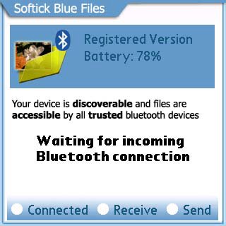
And just like that it was installed.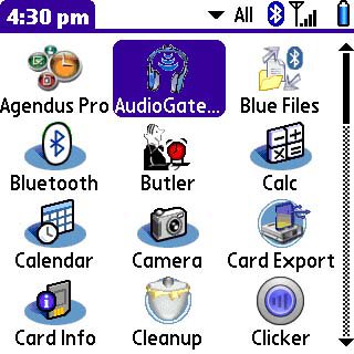
I then initiated the program and the first thing that appeared was a configuration wizard.
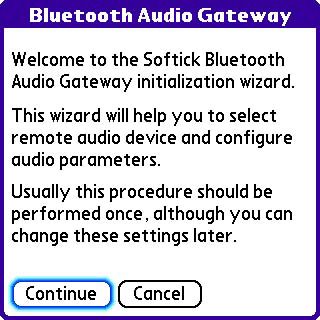
Upon selecting continue, it took me to a screen instructing me to set my Bluetooth headset into search mode. For my IoGear Stereo Headphones, I held the center button for 6 seconds.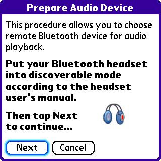
The Treo 650 promptly discovered the headset. Since I had already set up the headset as a trusted device and used it for phone calls, it was already to go.
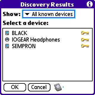
After selecting the IOGEAR headphones, I was taken to a Audio Gateway Configuration screen. I just left everything the same and selected done.
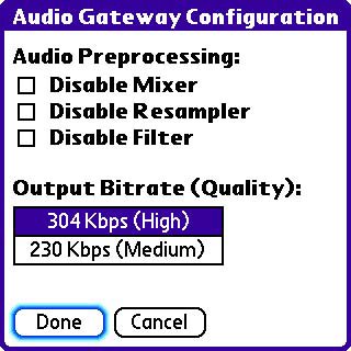
That is it as far a setup is concerned. Upon starting the Audio Gateway program after the setup procedure, you simply get a screen that allows one to select between internal and wireless audio. A configuration and test option is also available.
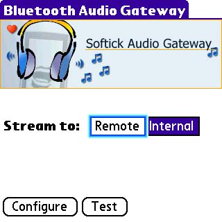
I selected "remote" and it quickly went thru a quick connection process...

And after a few seconds you get the main screen showing the setting.

I exited the program and went to Pocket Tunes.... Expecting something to crash or for some strange sound to emanate from one side of my headset or my Treo.
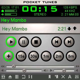
WOW!!! Good quality wireless stereo audio from my Treo!!!
Pocket Tunes does seem to hiccup a bit. I suspect that the Treo is being pushed to the limit. TCPMP seems to handle audio a little better. Once I put my Treo in my pocket and let the screen go off, the hiccuping disappeared. I still need to play with the setting to see if I can get better performance.
I did have some issues though. After receiving a phone call, my headset was unable to take the call. After taking the call manually and ending the call, Pocket Tunes resumed but via the rear speaker. I suspect a better quality headset would be able to take the call via Bluetooth and resume normally. My headphones are not listed as being supported but work great for just stereo audio.
If you are still reading this, you are wasting your time... Go run and get you Bluetooth stereo headphones and play with this awesome program yourself.

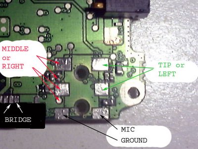
You will need to bridge MIC and GROUND where the 2 white arrows indicate "BRIDGE" this is so you can have internal mic functionality with the 3.5 mm stereo headset. The 2 pads labeled "TIP or LEFT" also need to be bridged together. The round pad labeled "MIDDLE or RIGHT' will be used to solder to the connector and the square pads need to also be bridged together. There is no need for a switch since the Treo has an electrical switch that senses when there is a Stereo headset pluged in.
After performing the above modifications to the board, you can now prepare the connector. I used a Kycon P/N ST-3500-3N. The connector needs to be shortened by 2 mm and a placement pin removed. The pin removal weakens the connector bond to the board, so you may want to use a non-conductive epoxy afterwards to secure the connector to the board. A before and after picture of the connector is shown below. Notice the edge of the connector is cut away to the metal contact. That metal contact will need to be soldered to the board since the tab had to be cut away.

Afere the connector modification, you can then place it to the board and solder it in place. Solder as shown below, making sure the solder point on the right is soldered to the contact deep in the connector. The other solder tab on the opposite side of the connector gets soldered to the round solder pad previously shown.

Once the connector is soldered in place. place the rear plastic on the board. Notice you will need to cut some plastic to get the board to sit flush. You will also need to trim more of the connector if it protrudes out like pictured below. It need to be flush with the plastic so that it does not interfere witht the battery. a normal OEM battery should be ok, but high-capacity batteries barely fit. Notice the jack tip in the pcture, it fits but any longer ant it would hit the battery.

below is a picture of two plastic shells joined together, notice they do not join correctly. You will need to cut the half circles on each plastic halve to make room for the bigger connector.
 Well, that is enough info I think. Please let me know if anyone else was brave enough to do this mod. I did it just to prove that it would work on a spare board.... It works!!! the board is now sitting in a box of treo junk...

I hope you guys like them and find them useful. Please let me know if there are any problems or suggestions.
Update:
I have been fixing the Treo 600 and 650 of this defective and broken jack problem. I charge $75 plus $10 for USPS Priority shipping with insurance. I usually ship your phone out the same day. The fix is a permant fix and will not require to be repaired ever again. I leave no external signs of tampering for warranty purposes.
It seems that apart from the poor volume , buggy software and other issues, the Treo 650 also suffers from an audio jack of poor quality. Their are different issues with the audio jack, but the most common are:
The first is a good solution for people that cannot or will not take apart their Treo. Their is a drawback though, in that the electrical switch is also overridden and one needs to make the switch manually from internal speaker to headset.
The second fix requires some work, but will still keep the same fuctionality. It should only be attempted by people familiar with electronics and soldering. That fix is described next.
The tools needed for the job are:
first, take apart the Treo 650, as described in my Dissassembly Instructions. After taking apart the Treo, look at the ajck to see if there is any damage. You probably will not see any damage, unless the jack was broken by force, the damage will be internally. below is a close-up of jack. Signal1 is for left channel audio or for mic (with mono headset). Signal3 is normally grounded, or mic only with the special 2-in-1 headset.
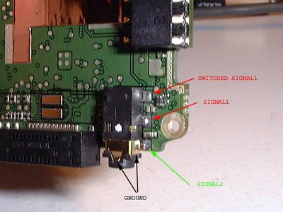
Create a copper wire bridge between the two pads labeled switched signal1 and signal1. This mechanical switch only causes problems and is not needed. Below is a picture of the other side of the connector.
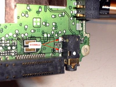
The electrical connection between the two signal2 pads should never be broken. Bridging the two pads together will make the jack more durable and will cure the "ghost jack" problem.
Please send me feedback or ask for help if needed.